24 / 07 / 02
「一生一芯」HDLBits
Getting Started
Step one
Build a circuit with no inputs and one output. That output should always drive 1 (or logic high).
module top_module( output one );

    assign one = 1'b1;

endmodule
Zero
Build a circuit with no inputs and one output that outputs a constant 0.
module top_module(
    output zero
);

    assign zero = 1'b0;

endmodule
Verilog language
Wire
Create a module with one input and one output that behaves like a wire.
module top_module( input in, output out );

    assign out = in;

endmodule
Wire4
Create a module with 3 inputs and 4 outputs that behaves like wires that makes these connections:
-
a -> w
-
b -> x
-
b -> y
-
c -> z
module top_module(
    input a,b,c,
    output w,x,y,z );

    assign w = a;
    assign x = b;
    assign y = b;
    assign z = c;

    //The solution using the concatenation operator is more elegant.
    //assign {w,x,y,z} = {a,b,b,c};

endmodule
Notgate
Create a module that implements a NOT gate.
module top_module( input in, output out );

    assign out = !in;

endmodule
Verilog has separate bitwise-NOT (~) and logical-NOT (!) operators, like C. Since we're working with a one-bit here, it doesn't matter which we choose.
Andgate
Create a module that implements an AND gate.
module top_module(
    input a,
    input b,
    output out );

    assign out = a & b;

endmodule
Verilog has separate bitwise-OR (|) and logical-OR (||) operators, like C. Since we're working with a one-bit here, it doesn't matter which we choose.
Norgate
Create a module that implements a NOR gate.
module top_module(
    input a,
    input b,
    output out );

    assign out = !(a|b);

endmodule
Verilog has separate bitwise-OR (|) and logical-OR (||) operators, like C. Since we're working with a one-bit here, it doesn't matter which we choose.
Xnorgate
module top_module(
    input a,
    input b,
    output out );

    assign out = !(a ^ b);

endmodule
The bitwise-XOR operator is ^. There is no logical-XOR operator.
Declaring wires
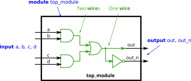
module top_module(
    input a,
    input b,
    input c,
    input d,
    output out,
    output out_n   );

    wire or_in[1:0];

    assign or_in[1] = a&b;
    assign or_in[0] = c&d;

    assign out = or_in[1]|or_in[0];
    assign out_n = !out;

endmodule
7458
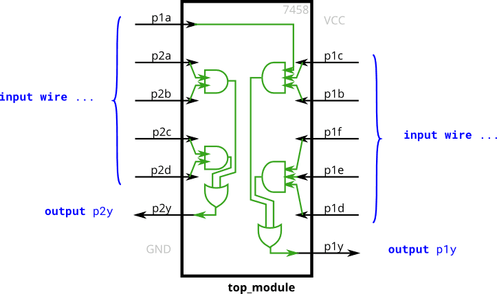
module top_module (
    input p1a, p1b, p1c, p1d, p1e, p1f,
    output p1y,
    input p2a, p2b, p2c, p2d,
    output p2y );

    assign p1y = (p1a&p1b&p1c)|(p1d&p1e&p1f);
    assign p2y = (p2a&p2b)|(p2c&p2d);

endmodule
Vectors
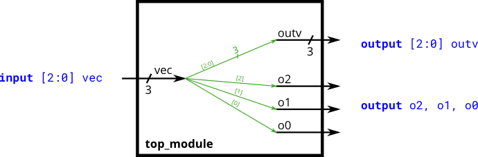
odule top_module (
    input wire [2:0] vec,
    output wire [2:0] outv,
    output wire o2,
    output wire o1,
    output wire o0 );

    assign outv[2:0]=vec[2:0];

    assign o2 = vec[2];
    assign o1 = vec[1];
    assign o0 = vec[0];

endmodule
Vectors in more detail
Build a combinational circuit that splits an input half-word (16 bits, [15:0] ) into lower [7:0] and upper [15:8] bytes.
module top_module(
    input wire [15:0] in,
    output wire [7:0] out_hi,
    output wire [7:0] out_lo );

    assign out_hi = in[15:8];
    assign out_lo = in[7:0];

    //The solution using the concatenation operator is more elegant.
    //assign {out_hi, out_lo} = in;

endmodule
Vector part select
A 32-bit vector can be viewed as containing 4 bytes (bits [31:24], [23:16], etc.). Build a circuit that will reverse the byte ordering of the 4-byte word.
AaaaaaaaBbbbbbbbCcccccccDddddddd => DdddddddCcccccccBbbbbbbbAaaaaaaa
module top_module(
    input [31:0] in,
    output [31:0] out );

    assign out[31:24] = in[ 7: 0];
    assign out[23:16] = in[15: 8];
    assign out[15: 8] = in[23:16];
    assign out[ 7: 0] = in[31:24];

endmodule
Vectorgates
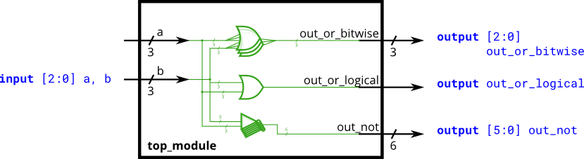
module top_module(
    input [2:0] a,
    input [2:0] b,
    output [2:0] out_or_bitwise,
    output out_or_logical,
    output [5:0] out_not
);

    assign out_or_bitwise = a|b;
    assign out_or_logical = a||b;
    assign out_not = ~{b,a};

endmodule
Four-input gates
Build a combinational circuit with four inputs, in[3:0]. There are 3 outputs:
-
out_and: output of a 4-input AND gate.
-
out_or: output of a 4-input OR gate.
-
out_xor: output of a 4-input XOR gate.
module top_module(
    input [3:0] in,
    output out_and,
    output out_or,
    output out_xor
);

    assign out_and = ∈
    assign out_or = |in;
    assign out_xor = ^in;

endmodule
Vector concatenation operator
Given several input vectors, concatenate them together then split them up into several output vectors. There are six 5-bit input vectors: a, b, c, d, e, and f, for a total of 30 bits of input. There are four 8-bit output vectors: w, x, y, and z, for 32 bits of output. The output should be a concatenation of the input vectors followed by two 1 bits:
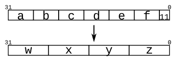
module top_module (
    input [4:0] a, b, c, d, e, f,
    output [7:0] w, x, y, z );//

    assign { w, x, y, z } = { a, b, c, d, e, f, 2'b11 };

endmodule
Vector reversal 1
Given an 8-bit input vector [7:0], reverse its bit ordering.
module top_module(
    input [7:0] in,
    output [7:0] out
);

    assign out = {in[0], in[1], in[2], in[3], in[4], in[5], in[6], in[7]};

endmodule
-
Code
assign out[7:0] = in[0:7];does not work because Verilog does not allow vector bit ordering to be flipped. -
The concatenation operator may save a bit of coding, allowing for 1 assign statement instead of 8.
If you want to know more about reversal vector by a loop, go to https://hdlbits.01xz.net/wiki/Vectorr and see the solution part.
Replication operator
Build a circuit that sign-extends an 8-bit number to 32 bits. This requires a concatenation of 24 copies of the sign bit (i.e., replicate bit[7] 24 times) followed by the 8-bit number itself.
module top_module (
    input [7:0] in,
    output [31:0] out );

    assign out = { {24{in[7]}} , in };

endmodule
More replication
Given five 1-bit signals (a, b, c, d, and e), compute all 25 pairwise one-bit comparisons in the 25-bit output vector. The output should be 1 if the two bits being compared are equal.
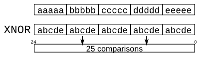
module top_module (
    input a, b, c, d, e,
    output [24:0] out );//

    // The output is XNOR of two vectors created by
    // concatenating and replicating the five inputs.
    assign out = ~{ {5{a}},{5{b}},{5{c}},{5{d}},{5{e}} } ^ { {5{a,b,c,d,e}} };

endmodule
Module
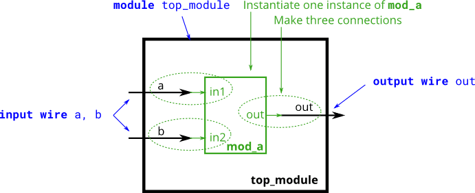 The code for module
 mod_a looks like this: mod_a ( input in1, input in2, output out );
module top_module ( input a, input b, output out );

    mod_a instance1 ( .in1(a), .in2(b), .out(out) );

endmodule
Connecting ports by position
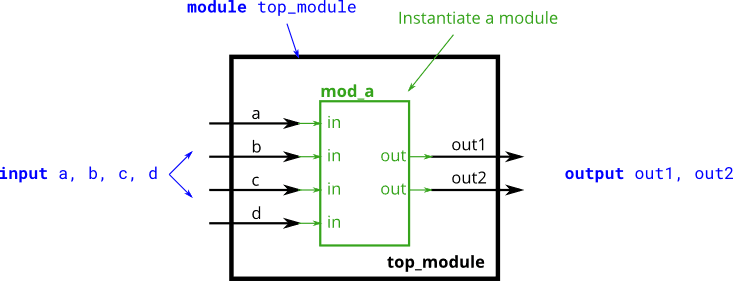 You are given the following module:
 module mod_a ( output, output, input, input, input, input );
module top_module (
    input a,
    input b,
    input c,
    input d,
    output out1,
    output out2
);

    mod_a instance1 ( out1, out2, a, b, c, d );

endmodule
Connecting ports by name
You are given a module named mod_a that has 2 outputs and 4 inputs, in some order. You must connect the 6 ports by name to your top-level module's ports:
Port in mod_a | Port in top_module |
|---|---|
output out1 | out1 |
output out2 | out2 |
input in1 | a |
input in2 | b |
input in3 | c |
input in4 | d |
module top_module (
    input a,
    input b,
    input c,
    input d,
    output out1,
    output out2
);

    mod_a instance1 ( .in1(a), .in2(b), .in3(c), .in4(d), .out1(out1), .out2(out2) );

endmodule
Three modules
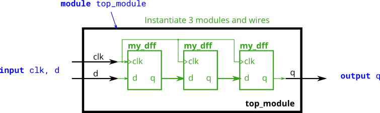 The module provided to you is:
 module my_dff ( input clk, input d, output q );
module top_module ( input clk, input d, output q );

    wire q1, q2;

    my_dff instance1 ( .clk(clk), .d( d), .q(q1) );
    my_dff instance2 ( .clk(clk), .d(q1), .q(q2) );
    my_dff instance3 ( .clk(clk), .d(q2), .q(q ) );

endmodule
Modules and vectors
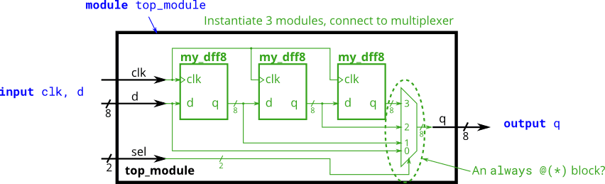 The module provided to you is:
 module my_dff8 ( input clk, input [7:0] d, output [7:0] q );
module top_module (
    input clk,
    input [7:0] d,
    input [1:0] sel,
    output [7:0] q
);

    wire [7:0] q1, q2, q3;

    my_dff8 d1 ( clk,  d, q1 );
    my_dff8 d2 ( clk, q1, q2 );
    my_dff8 d3 ( clk, q2, q3 );

    always @(*) begin
        case(sel)
            2'b00: q = d;
            2'b01: q = q1;
            2'b10: q = q2;
            2'b11: q = q3;
        endcase
    end

endmodule
Adder 1
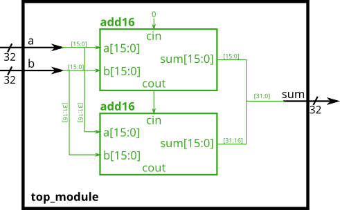 Connect the modules together as shown in the diagram below. The provided module
 add16 has the following declaration: module add16 ( input[15:0] a, input[15:0] b, input cin, output[15:0] sum, output cout );
module top_module(
    input [31:0] a,
    input [31:0] b,
    output [31:0] sum
);

    wire cout1;

    add16 a1 ( a[15: 0], b[15: 0],  1'b0, sum[15: 0], cout1 );
    add16 a2 ( a[31:16], b[31:16], cout1, sum[31:16], );

endmodule
Adder 2
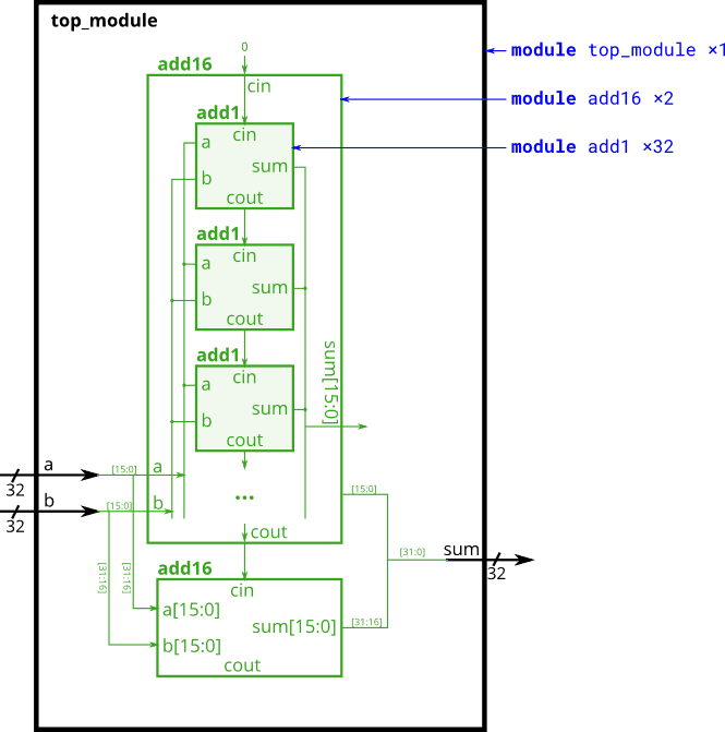 The provided module
 add16 has the following declaration: module add16 ( input[15:0] a, input[15:0] b, input cin, output[15:0] sum, output cout );
Within each add16, 16 full adders (module add1, not provided) are instantiated to actually perform the addition. You must write the full adder module that has the following declaration: module add1 ( input a, input b, input cin, output sum, output cout );
module top_module (
    input [31:0] a,
    input [31:0] b,
    output [31:0] sum
);

    wire cout1;

    add16 a1 ( a[15: 0], b[15: 0],  1'b0, sum[15: 0], cout1 );
    add16 a2 ( a[31:16], b[31:16], cout1, sum[31:16], );

endmodule

module add1 ( input a, input b, input cin,   output sum, output cout );

    wire [1:0] result;

    assign result = a + b + cin;
    assign { cout, sum } = result;

endmodule
Carry-select adder
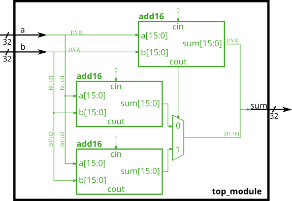 The provided module
 add16 has the following declaration: module add16 ( input[15:0] a, input[15:0] b, input cin, output[15:0] sum, output cout );
module top_module(
    input [31:0] a,
    input [31:0] b,
    output [31:0] sum
);

    wire cout1;
    wire [31:0] re;

    add16 a1 ( a[15: 0], b[15: 0], 1'b0, sum[15: 0], cout1 );
    add16 a2 ( a[31:16], b[31:16], 1'b0, re[15: 0], );
    add16 a3 ( a[31:16], b[31:16], 1'b1, re[31:16], );

    always @(*)
        case(cout1)
            1'b0: sum[31:16] = re[15: 0];
            1'b1: sum[31:16] = re[31:16];
        endcase

endmodule
Adder-subtractor
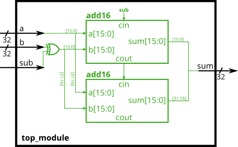 You are provided with a 16-bit adder module, which you need to instantiate twice:
 module add16 ( input[15:0] a, input[15:0] b, input cin, output[15:0] sum, output cout );
module top_module(
    input [31:0] a,
    input [31:0] b,
    input sub,
    output [31:0] sum
);

    wire cout1;

    add16 a1 ( a[15: 0], (b[15: 0]^{16{sub}}),   sub, sum[15: 0], cout1 );
    add16 a2 ( a[31:16], (b[31:16]^{16{sub}}), cout1, sum[31:16], );

endmodule
Always blocks (combinational)
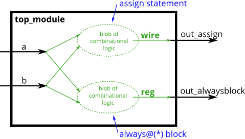 Build an AND gate using both an assign statement and a combinational always block.
module top_module(
    input a,
    input b,
    output wire out_assign,
    output reg out_alwaysblock
);

    assign out_assign = a & b;
    always @(*) out_alwaysblock = a & b;

endmodule
Always blocks (clocked)
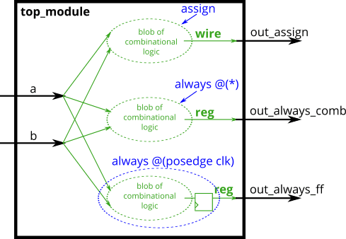 Build an XOR gate three ways, using an assign statement, a combinational always block, and a clocked always block.
module top_module(
    input clk,
    input a,
    input b,
    output wire out_assign,
    output reg out_always_comb,
    output reg out_always_ff   );

    assign out_assign = a ^ b ;

    always@(*) out_always_comb = a ^ b ;

    always@(posedge clk) out_always_ff <= a ^ b ;

endmodule
If statement
Build a 2-to-1 mux that chooses between a and b. Choose b if both sel_b1 and sel_b2 are true. Otherwise, choose a. Do the same twice, once using assign statements and once using a procedural if statement.
| sel_b1 | sel_b2 | **out_assign
out_always** | | --- | --- | --- | | 0 | 0 | a | | 0 | 1 | a | | 1 | 0 | a | | 1 | 1 | b |
module top_module(
    input a,
    input b,
    input sel_b1,
    input sel_b2,
    output wire out_assign,
    output reg out_always   );

    always @(*) begin
        if ( sel_b1 & sel_b2 == 1 ) begin
            out_always = b;
        end
        else begin
            out_always = a;
        end
    end

    assign out_assign = ( sel_b1 & sel_b2 == 1 ) ? b : a;

endmodule
If statement latches
The following code contains incorrect behaviour that creates a latch. Fix the bugs so that you will shut off the computer only if it's really overheated, and stop driving if you've arrived at your destination or you need to refuel.
always @(*) begin
    if (cpu_overheated)
       shut_off_computer = 1;
end

always @(*) begin
    if (~arrived)
       keep_driving = ~gas_tank_empty;
end
module top_module (
    input      cpu_overheated,
    output reg shut_off_computer,
    input      arrived,
    input      gas_tank_empty,
    output reg keep_driving  ); //

    always @(*) begin
        if (cpu_overheated)
           shut_off_computer <= 1;
        else shut_off_computer <= cpu_overheated;
    end

    always @(*) begin
        if (~arrived)
           keep_driving <= ~gas_tank_empty;
        else keep_driving <= 0;
    end

endmodule
Case statement
When sel is between 0 and 5, choose the corresponding data input. Otherwise, output 0. The data inputs and outputs are all 4 bits wide.
module top_module (
    input [2:0] sel,
    input [3:0] data0,
    input [3:0] data1,
    input [3:0] data2,
    input [3:0] data3,
    input [3:0] data4,
    input [3:0] data5,
    output reg [3:0] out   );//

    always@(*) begin  // This is a combinational circuit
        case (sel)
            3'b000: out = data0;
            3'b001: out = data1;
            3'b010: out = data2;
            3'b011: out = data3;
            3'b100: out = data4;
            3'b101: out = data5;
          default: out = 4'b0000;
        endcase
    end

endmodule
Priority encoder
Build a 4-bit priority encoder. For this problem, if none of the input bits are high (i.e., input is zero), output zero. Note that a 4-bit number has 16 possible combinations.
module top_module (
    input [3:0] in,
    output reg [1:0] pos  );

    always @(*) begin
        casez (in)
            4'bzzz1: pos = 0;
            4'bzz1z: pos = 1;
            4'bz1zz: pos = 2;
            4'b1zzz: pos = 3;
            default: pos = 0;
        endcase
    end

endmodule
Priority encoder with casez
Build a priority encoder for 8-bit inputs. Given an 8-bit vector, the output should report the first (least significant) bit in the vector that is 1. Report zero if the input vector has no bits that are high. For example, the input 8'b10010000 should output 3'd4, because bit[4] is first bit that is high.
module top_module (
    input [7:0] in,
    output reg [2:0] pos );

    always @(*) begin
        casez (in)
            8'bzzzzzzz1: pos = 0;
            8'bzzzzzz1z: pos = 1;
            8'bzzzzz1zz: pos = 2;
            8'bzzzz1zzz: pos = 3;

            8'bzzz1zzzz: pos = 4;
            8'bzz1zzzzz: pos = 5;
            8'bz1zzzzzz: pos = 6;
            8'b1zzzzzzz: pos = 7;

            default: pos = 0;
        endcase
    end

endmodule
Avoiding latches
| Scancode [15:0] | Arrow key |
|---|---|
| 16'he06b | left arrow |
| 16'he072 | down arrow |
| 16'he074 | right arrow |
| 16'he075 | up arrow |
| Anything else | none |
Your circuit has one 16-bit input, and four outputs. Build this circuit that recognizes these four scancodes and asserts the correct output.
module top_module (
    input [15:0] scancode,
    output reg left,
    output reg down,
    output reg right,
    output reg up  );

    always @(*) begin
        up = 1'b0; down = 1'b0; left = 1'b0; right = 1'b0;
        case (scancode)
            16'he06b: left = 1;
            16'he072: down = 1;
            16'he074: right = 1;
            16'he075: up = 1;
        endcase
    end

endmodule
This style of code ensures the outputs are assigned a value (of 0) in all possible cases unless the case statement overrides the assignment. This also means that a default: case item becomes unnecessary.
Conditional ternary operator
Given four unsigned numbers, find the minimum.
module top_module (
    input [7:0] a, b, c, d,
    output [7:0] min);

    wire [7:0] min1,min2;

    assign min1 = ((a < b) ? a : b);
    assign min2 = ((c < d) ? c : d);
    assign min = (min1 < min2) ? min1 : min2;

endmodule
Reduction operators
Create a circuit that will compute a parity bit for a 8-bit byte (which will add a 9th bit to the byte). We will use "even" parity, where the parity bit is just the XOR of all 8 data bits.
module top_module (
    input [7:0] in,
    output parity);

    assign parity = ^ in[7:0];

endmodule
Reduction: Even wider gates
Build a combinational circuit with 100 inputs, in[99:0].
There are 3 outputs:
-
out_and: output of a 100-input AND gate.
-
out_or: output of a 100-input OR gate.
-
out_xor: output of a 100-input XOR gate.
module top_module(
    input [99:0] in,
    output out_and,
    output out_or,
    output out_xor
);

    assign out_and = & in[99:0];
    assign out_or  = | in[99:0];
    assign out_xor = ^ in[99:0];

endmodule
Combinational for-loop: Vector reversal 2
Given a 100-bit input vector [99:0], reverse its bit ordering.
module top_module(
    input [99:0] in,
    output [99:0] out
);

    integer i;
    always@(*)begin
        for(i=0;i<100;i=i+1)begin
             out[99-i] = in[i];
        end
    end

endmodule
Combinational for-loop: 255-bit population count
A "population count" circuit counts the number of '1's in an input vector. Build a population count circuit for a 255-bit input vector.
module top_module(
    input [254:0] in,
    output [7:0] out );

    integer i;
    always@(*)begin
        out = 0;
        for(i = 0; i < 255; i = i + 1)
            if (in[i] == 1) out = out + 1;
    end

endmodule
Generate for-loop: 100-bit binary adder 2
Create a 100-bit binary ripple-carry adder by instantiating 100 full adders. The adder adds two 100-bit numbers and a carry-in to produce a 100-bit sum and carry out. To encourage you to actually instantiate full adders, also output the carry-out from each full adder in the ripple-carry adder. cout[99] is the final carry-out from the last full adder, and is the carry-out you usually see.
module top_module(
    input [99:0] a, b,
    input cin,
    output [99:0] cout,
    output [99:0] sum );

    integer i;
    always @(*) begin
        sum[0] = a[0] ^ b[0] ^ cin;
        cout[0] = a[0] & b[0] | cin & (a[0]|b[0]);
        for (i = 1; i<100; i++) begin
            sum[i] = a[i] ^ b[i] ^ cout[i-1];
            cout[i] = a[i] & b[i] | cout[i-1] & (a[i]|b[i]);
        end
    end

endmodule
Generate for-loop: 100-digit BCD adder
You are provided with a BCD one-digit adder named bcd_fadd that adds two BCD digits and carry-in, and produces a sum and carry-out.
module bcd_fadd (
    input [3:0] a,
    input [3:0] b,
    input     cin,
    output   cout,
    output [3:0] sum );
Instantiate 100 copies of bcd_fadd to create a 100-digit BCD ripple-carry adder. Your adder should add two 100-digit BCD numbers (packed into 400-bit vectors) and a carry-in to produce a 100-digit sum and carry out.
module top_module(
    input [399:0] a, b,
    input cin,
    output cout,
    output [399:0] sum );

    wire [98:0]c;

    bcd_fadd u_bcd_fadd[99:0](
        .a(a[399:0]),
        .b(b[399:0]),
        .cin({c[98:0],cin}),
        .cout({cout,c[98:0]}),
        .sum(sum[399:0])
    );
endmodule
后续部分就不在这里水了(逃)
Verilog 代码积累
边沿检测
module edge_detect(
	input clk,
	input rst,
	input signal,
	output pos_edge,
	output neg_edge,
	output both_edge);

	reg sig_r0, sig_r1;
	always @(posedge clk) begin
	if (rst)
	    begin
			sig_r0 <= 1'b0;
			sig_r1 <= 1'b0;
		end
	else
		begin
			sig_r0 <= signal;
			sig_r1 <= sig_r0;
		end
	end

	assign pos_edge = ~sig_r1 & sig_r0;
	assign neg_edge = sig_r1 & ~sig_r0;
	assign both_edge = sig_r0 ^ sig_r1;

endmodule